Understanding Modbus
Client and Server (or Master and Slave?)
One of the biggest sources of confusion on-site is the terminology. Older Modbus documentation and many devices still use master and slave. Newer standards use client and server. They mean the same thing:
| Old term | New term | Role |
|---|---|---|
| Master | Client | Sends requests, asks for data |
| Slave | Server | Responds to requests, provides data |
You'll see both naming conventions used interchangeably in datasheets, PLC manuals, and configuration software. A "Modbus master" is the same as a "Modbus client". If a colleague says "the slave isn't responding", they mean the server.
This naming confusion causes real problems in the field. When you're working with mixed documentation (one manual says "master", another says "client"), just remember: the one asking questions is the client/master, the one answering is the server/slave.
TCP or RTU
Modbus comes in two variants that determine how messages are transmitted:
Modbus TCP works over a regular network (Ethernet/Wi-Fi). You need an IP address and port. No special hardware required. This is the most common variant in modern installations.
Modbus RTU works over a serial connection (RS-485). RTU is common in older installations and industrial environments where devices are directly connected by cable.
Unit ID
The Unit ID identifies which server should respond to a request. How it works depends on the variant:
With RTU the Unit ID is always required. Multiple devices share the same serial bus, and the Unit ID is the only way to address a specific one. Each device on the bus has its own unique Unit ID.
With TCP the Unit ID is often optional. Each device typically has its own IP address, so the Unit ID is redundant. You can usually leave it at 0.
RTU-to-TCP converters are where it gets interesting. These converters bridge a TCP network to a serial RTU bus. You connect via TCP (IP address and port), but behind the converter there may be multiple RTU devices. In that case the Unit ID is required to route your request to the correct device on the bus.
Don't know which Unit IDs are behind a converter, or which one a device on a bus was configured with? A Unit ID scan asks each one in turn and tells you which answered, which refused, and which stayed silent. Commissioning documentation is wrong about this more often than about anything else, because the Unit ID is usually set with a DIP switch by whoever mounted the device.
Register types
Modbus organizes data into four types of registers. Each type has its own purpose, described here from the client's perspective:
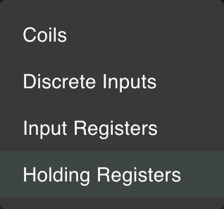
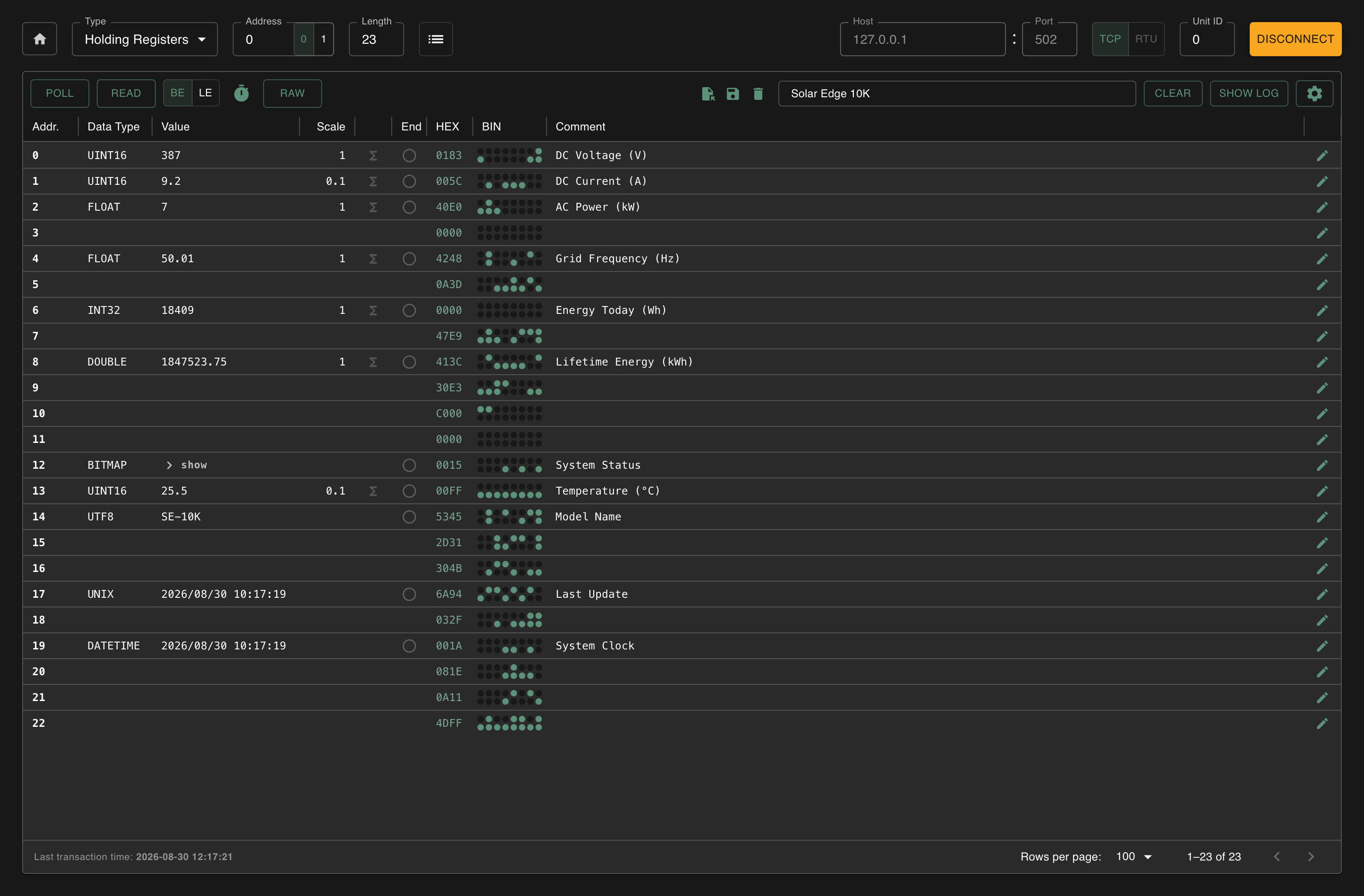
Holding Registers: read and write
The workhorses of Modbus. The client can both read and write these. Used for setpoints, configuration parameters, alarm thresholds.
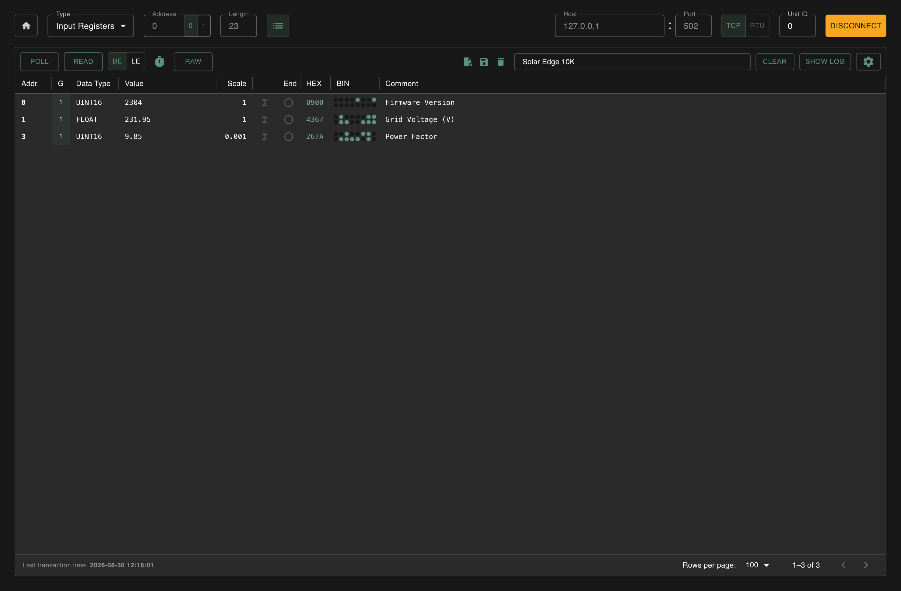
Input Registers: read only
Sensor data and measurements. The server populates these with values (e.g. a temperature reading) and the client reads them out. The client can't write to them.
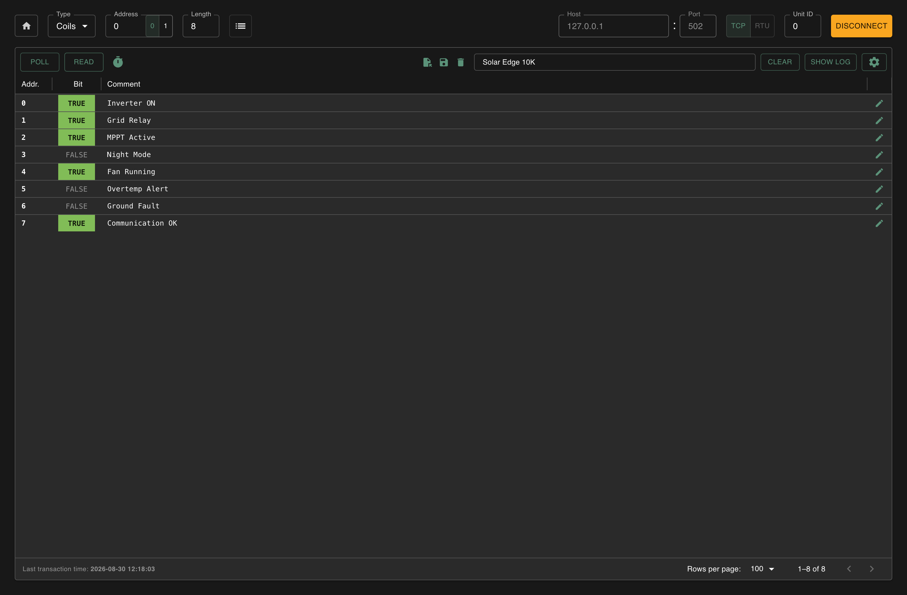
Coils: read and write (on/off)
Digital outputs. The client can turn them on or off, for example a pump or a valve. Each coil is one bit: 0 (off) or 1 (on).
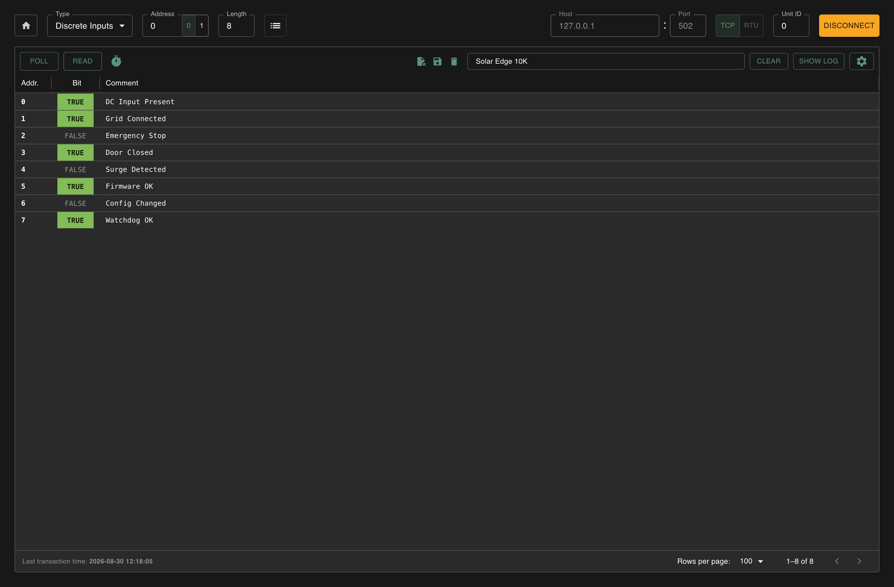
Discrete Inputs: read only (on/off)
Digital inputs. The server sets these based on physical state (a switch, a sensor). The client can only read them. Like coils they're binary, but read only.
In practice, most systems mainly use Holding and Input Registers. Coils and Discrete Inputs are less common because a single 16-bit register can hold 16 statuses at once.
Addressing
The address problem
The wire carries one number, from 0 to 65535. Manuals print something else, and
rarely the same something. These are all the first holding register, the one
Modbux reads at address 0:
| What the manual writes | Notation | Second register | Third |
|---|---|---|---|
0 | Protocol address, what goes on the wire | 1 | 2 |
1 | 1-based, no prefix | 2 | 3 |
40001 | 5-digit Modicon, counting from 1 | 40002 | 40003 |
40000 | 5-digit, counting from 0 | 40001 | 40002 |
400001 | 6-digit Modicon | 400002 | 400003 |
4x0001 | Modicon 4x notation | 4x0002 | 4x0003 |
Two independent choices produce that list: whether the number carries a type prefix, and whether counting starts at 0 or 1. Rows three and four make both choices differently and land one apart, which is the argument people keep having about "register 40001".
Modicon, in case you were wondering, is the company that invented Modbus in
1979. The 4xxxx numbering comes from how their PLCs laid out memory.
When 40001 really is 40001
There is a seventh reading: 40001 is also an ordinary address. SunSpec solar
inverters put their register map at 40000 and upward, and those are real
addresses on the wire.
The decisive test is the ceiling. A manual listing anything above 49999 cannot
be using the 5-digit prefix scheme, because that scheme has no room past
4x9999. If it also prints a separate 3xxxx table for input registers, it is
using prefixes.
Guess wrong here and the two readings are 40001 apart, so you get an exception or a register from a different part of the device. This mistake announces itself instead of quietly returning plausible nonsense.
Working it out
Strip the prefix, then fix the base:
40001→ drop the4→0001→ counting from 1, subtract 1 → 030011→ an input register →0011→ 10
To find the base, look at the manual's lowest address. 40001 counts from 1,
40000 from 0, and a table starting at 0 is already protocol addresses.
Or ask the device
When the documentation is the problem, stop reading it.
Scan both candidate ranges, 0 to 200 and 39900 to 40100. Whichever comes back full settles it. Then read the values rather than the addresses: a grid voltage sits near 230 and a frequency near 50, so the row with a plausible number is your register. Compare its address with the manual's and that offset holds for the whole device.
The prefix, when there is one
| Prefix | Register type | Function code |
|---|---|---|
0xxxx | Coils | FC1 / FC5 / FC15 |
1xxxx | Discrete Inputs | FC2 |
3xxxx | Input Registers | FC4 |
4xxxx | Holding Registers | FC3 / FC6 / FC16 |
Siemens TIA Portal's MB_CLIENT block works this way. MB_MODE says read or
write, and MB_DATA_ADDR carries the type and the address together:
MB_MODE | MB_DATA_ADDR | Reads or writes | Function code |
|---|---|---|---|
0 | 1 – 9999 | Coils | FC1 |
0 | 10001 – 19999 | Discrete Inputs | FC2 |
0 | 30001 – 39999 | Input Registers | FC4 |
0 | 40001 – 49999 | Holding Registers | FC3 |
1 | 1 – 9999 | Coils | FC5 or FC15 |
1 | 40001 – 49999 | Holding Registers | FC6 or FC16 |
On the write rows MB_DATA_LEN picks between the single and multiple function
codes. Past 9999 registers the block takes 400001 to 465535, where 400001
is address 0, so 465535 is 65534: the last register a device can have is
the one address this notation cannot write down.
MB_MODE also takes the function code directly. 101 to 106, 115 and
116 name FC1 to FC6, FC15 and FC16, and then MB_DATA_ADDR is a plain
address with no prefix. That is the mode for a device with real addresses,
such as that SunSpec map. Full table in Siemens'
parameter reference.
Function codes
Under the hood, Modbus uses numbered commands (function codes) for each operation. You don't need to memorize them, but they help when debugging:
| FC | What it does |
|---|---|
| FC 01 | Read coils |
| FC 02 | Read discrete inputs |
| FC 03 | Read holding registers |
| FC 04 | Read input registers |
| FC 05 | Write a single coil |
| FC 06 | Write a single holding register |
| FC 15 | Write multiple coils |
| FC 16 | Write multiple holding registers |
Big-Endian vs Little-Endian
When a value needs more than 16 bits (like a 32-bit integer or float), it gets split across multiple 16-bit registers. The question is: which register gets the "high" part and which gets the "low" part? That's what endianness determines.
Take the 32-bit integer 305419896 (hex 0x12345678) split across two registers. Switch between the tabs to see what changes:
Register 0:  0x1234  (W1 - high word)
Register 1: 0x5678 (W0 - low word)registers[0] := W1; // most significant word first
registers[1] := W0;Most significant word first. This is the Modbus standard and what most PLCs use.
Register 0:  0x5678  (W0 - low word)
Register 1: 0x1234 (W1 - high word)registers[0] := W0; // least significant word first
registers[1] := W1;Least significant word first. Less common in Modbus, but some devices use it.
If your values look nonsensical (a temperature reading of millions, or a counter that makes no sense), the endianness is probably wrong. This is one of the most common issues when connecting to a new device.
Use the BE/LE toggle in the Modbux toolbar. It reads again when you switch, so the values on screen update straight away and you can see which order is right rather than working it out. In Server mode, endianness is a global setting per server, so all registers on a server share the same word order, matching how real devices typically work.